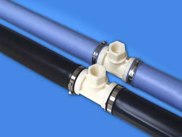
Three-Way Liftable Tube Aerator
Model: KTSB
Specifications: Customizable
The KTSB liftable microporous aerator is a new type of aerator developed by our company during the aeration system renovation process. It incorporates the advantages of similar foreign products and can be installed without interrupting water or air supply. This product can be applied to the construction and renovation of various activated sludge aeration tanks for urban sewage and industrial wastewater.
Product Descriptions
Product Materials
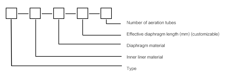
Ø Main Gas Supply Pipe: Carbon steel, 304 stainless steel, galvanized steel pipe
Ø Branch Gas Supply Pipe: Carbon steel, 304 stainless steel, galvanized steel pipe
Ø Aerator Diaphragm: EPDM, silicone, polyurethane
Ø Aerator Liner: ABS, UPVC
Aerator Performance Advantages
Ø The liftable tube aerator can be directly lifted out of the water for cleaning and maintenance, keeping the aeration system in optimal condition, thereby reducing blower losses, maintaining high power efficiency, and lowering operating costs;
Ø Uniform aeration, fine bubbles, high oxygen utilization, and high power efficiency;
Ø Good flow velocity and flow pattern, low resistance, and low energy consumption;
Ø Reasonable structure, easy installation, and long service life thanks to the 304 stainless steel support body;
Ø Convenient installation, can be installed in both water-filled and water-free pools, requires no additional configuration within the pool, and can be easily lifted for maintenance during extended aeration periods without draining water or shutting down the blower, ensuring uninterrupted operation;
Ø No need for air purification, backwashing, or vent valves, making management more convenient;
Ø Various aerators originally fixed at the bottom of the pool can be directly converted to this liftable tube microporous aerator, provided the original air inlet pipe remains unchanged.
Product Specifications and Technical Parameters
Common Product Faults and Solutions
| Serial Numbe | Fault Phenomenon | Fault Cause | Solution |
| 1 | The aeration rate varies for each gas supply pipe | The gas supply volume varies for each gas supply pipe | Adjust the air inlet valve |
| 2 | Uneven aeration in certain areas | Aerator blockage | 1. Clean with acid washing equipment; 2. Close or reduce the air supply from other main air supply lines, and increase the air supply from this main line until aeration is uniform. 3. Remove and clean the aerator. |
| 3 | Air leakage at the center connector | Loose U-shaped clamp screw | Tighten the U-shaped clamp screw or replace the U-shaped clamp |
| 4 | Large air bubbles in some areas of the aerator | The diaphragm is torn | The aeration diaphragm needs to be replaced |
| 5 | Large air bubbles at both ends of the diaphragm | Diaphragm clamps are loose | Tighten the diaphragm clamps or replace them |
| 6 | Large air bubbles at the flange connection | Loose flange bolts | Tighten the flange bolts or replace them |
Product inspection and repair
Inspect the aeration tank daily and operate strictly according to the operating procedures. If uneven aeration or large local bubbles are found, analyze the cause of the fault and troubleshoot according to the previous article in this maintenance manual.
Membrane Replacement Steps
Ø First, remove the aerator;
Ø Check if the clamps are damaged;
Ø Loosen the clamps, remove the old membrane, and replace it with a new membrane;
Ø When tightening the clamps, the clamp rings must be parallel to the air distribution connection pipe.
Installation Steps
(I) Liftable aerators are generally evenly distributed at the bottom of the water treatment tank, 100-250mm from the bottom, with a longitudinal spacing of 300-1000mm.
(II) Installation of Components and Accessories
Main Gas Supply Pipe:
Ø Weld the pipeline into a single continuous pipe according to the dimensions shown in the drawings;
Ø Draw lines on the continuous pipe and weld the gas supply branch pipe joints. Weld one end of each branch pipe joint to the main gas supply pipe and the other end to a flange, ensuring that each branch pipe joint is on a horizontal line;
Ø Dimension a is approximately generally 300-500mm, depending on the user’s water level, ensuring the branch pipe flange is above the water surface for easy future maintenance; dimension b is approximately 1000-1200mm, representing the spacing between each aerator set;
Ø After welding the branch pipe joints, weld a blind flange to one end of the main gas supply pipe and a valve flange to the other end. Then place the main gas supply pipe in the actual position marked on the drawings.
Gas Supply Branch Pipe:
Ø Cut the gas supply branch pipe to the dimensions shown in the drawings, then weld a flange to each end.
During this process, ensure that the holes on both flanges align with the positions of the flanges on the gas supply branch pipe connector and the flange on the aerator itself.
Ø The dimension marked ‘a’ is determined based on parameters such as pool depth and water depth.
Aerator:
Ø The dimension marked ‘a’ is generally around 100-300mm. This equipment is a finished product; the owner only needs to fit the diaphragm onto the inner liner.
Ø The dimension marked ‘a’ is generally 1130mm, but can be customized according to customer specifications. The diaphragm is individually packaged during shipment to prevent wear during transport. When fitting the diaphragm, ensure the unperforated portion is vertical so that air is blown horizontally through the aeration holes, preventing diaphragm blockage when aeration stops. Tighten the diaphragm clamps at both ends to prevent leakage and detachment.
Ø Main Gas Supply Pipe Welding and Positioning
The main gas supply pipe is directly fixed to the wall using U-shaped clips;
The main gas supply pipe is placed on a support, which is then fixed to the tank body.
Ø Install Branch Gas Supply Pipes
Ø Install Aerators
Ø Adjust the aerators to ensure they are in a straight line;
Ø Check that all connection bolts are tightened to prevent air leaks;
Ø Installation Complete, Commissioning and Acceptance.