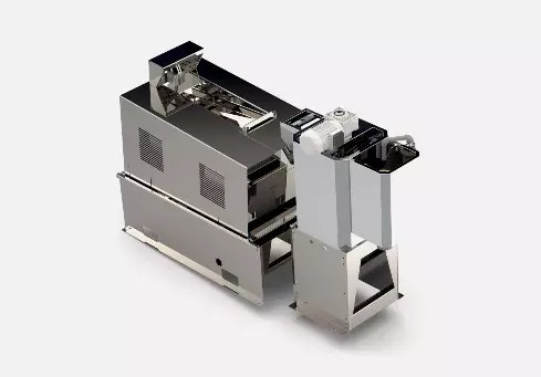
Plate Type Solid-Liquid Separator
The flat-plate solid-liquid separator adopts an integrated mechanical, electrical, and hydraulic design and manufacturing, including the separator body (primary mixing tank, secondary mixing tank, primary and secondary mixers, fixed grid bars, diamond-shaped rotating shaft, elliptical discs, dewatering section pressure plate, cylinder pressure mechanism, transmission reduction motor, transmission chain, transmission wheel, dewatering section filtrate tank, concentration section filtrate tank), main frame, sealing plate, piping system, material conveying system, and control system. It can realize automatic filtration, concentration, dewatering, and material conveying processes, controlled by an electrical cabinet or according to a program set by a PLC programmable controller.
Product Descriptions
Material Advance&concentration and Dehydration of Materials
A series of rhomboid rotating shafts are strung together with elliptical discs and placed under horizontally fixed grid bars. The thickness of the discs is less than the gaps between the grid bars, and the height of the grid bars is less than the axial length of the ellipse. After placement, approximately one-third of the elliptical discs are left outside the grid bars, with the majority below the grid bars. Axially, each set of rhomboid rotating shafts is positioned upwards, with only one disc between adjacent grid bars. The elliptical discs on adjacent rhomboid rotating shafts are at 90° angles to each other. Adjacent elliptical discs mesh during rotation but do not contact each other. Through this structure, driven by the wheel, the rhomboid rotating shafts drive the elliptical discs to rotate synchronously, gradually pushing the sludge on the fixed grid bars in waves towards the thickening section, dewatering section, and discharge point. The fixed grid bars have a spacing of 1mm. Sludge and other particulate matter in the material, after flocculation with added chemicals, form larger flocs. The diameter of these flocs is larger than the spacing between the grid bars. As the material is guided onto the fixed grid in the dewatering section, the larger particles are trapped by the grid bars and, with the rotation of the elliptical discs, are thrown into the area of the next elliptical disc, eventually being pushed into the concentration section. The majority of the water in the material, through force, passes directly through the bars into the filtrate cross section below the grid bars. As the material is continuously thrown and propelled, the water particles in the material are also evenly pushed to the outside and fall into the grid gaps. After the material is pushed into the concentration section, most of its free water has already been removed in the dewatering section. Gravity alone is insufficient to separate the adsorbed water from the flocs. At this stage, the elliptical discs gradually narrow, pushing the material into the inclined pressure plate. Pressure is applied to the material via a pressure cylinder on the pressure plate. As the gap between the pressure plate and the grid bars narrows, the material experiences increasing pressure as it progresses. Under the combined action of pressure and gravity, the free water and some adsorbed water in the flocs are squeezed out and enter the gaps between the grid bars, eventually falling into the concentrated filtrate tank below the concentration section. The material, dewatered by pressure, ultimately forms a sludge cake and is discharged from the outlet.
Product Advantage
01.Non-clogging
No backwashing required. Continuous rotation between continuously set elliptical rotor slits allows for simultaneous solid-liquid separation and self-cleaning.
02.Stable cleaning power.
Self-cleaning of the filter slits prevents capacity reduction due to clogging, unlike other filtration-type dewatering machines.
03.Powerful transport capacity.
The rotating elliptical rotor transports the separated solids.
04.Easy maintenance.
Due to its simple structure, maintenance is relatively easy.
Working Principle
| Model Number | Dry Sludge kg-DS/h | Processing Capacity | Dimensions(m)L*W*H | Power(kw) | Weight(kg) | |
| ≤10000mg/L | ≥20000mg/L | |||||
| DYPL-308 | 35-100 | ~4 | ~2 | 2.2*0.8*1.2 | 0.55 | 550 |
| DYPL-512 | 60-175 | ~7 | ~3.5 | 2.4*0.9*1.1 | 1.5 | 750 |
| DYPL-712 | 80-200 | ~10 | ~5 | 2.5*1.1*1.1 | 2.2 | 840 |
| DYPL-914 | 100-320 | ~13 | ~7 | 2.8*1.5*1.2 | 2.2 | 1100 |
| DYPL-1114 | 120-400 | ~16 | ~8 | 2.8*1.5*1.3 | 3 | 1300 |
| DYPL-1316 | 150-450 | ~19 | ~10 | 3*1.8*1.5 | 3 | 1500 |